Website powered by

Perfectly Remapping a Cube to a Sphere - Houdini

Tutorial / 04 August 2022


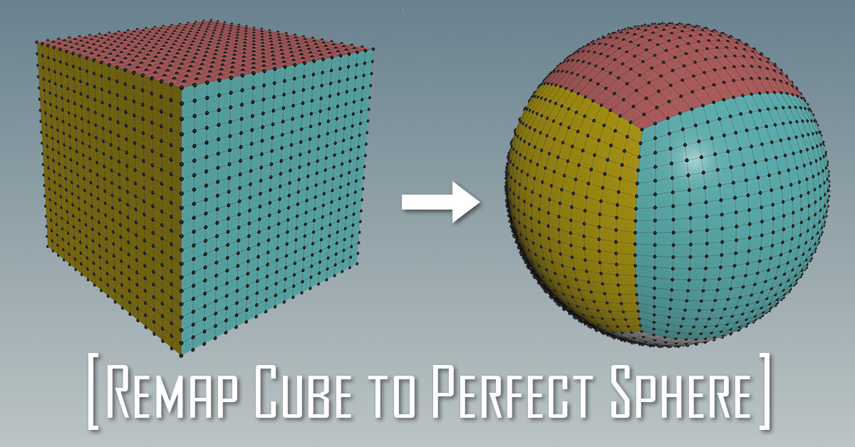
A perfectly rounded sphere, with clean and uniform topology. I'm sure every artist that works with 3D models needed something like this at some point.
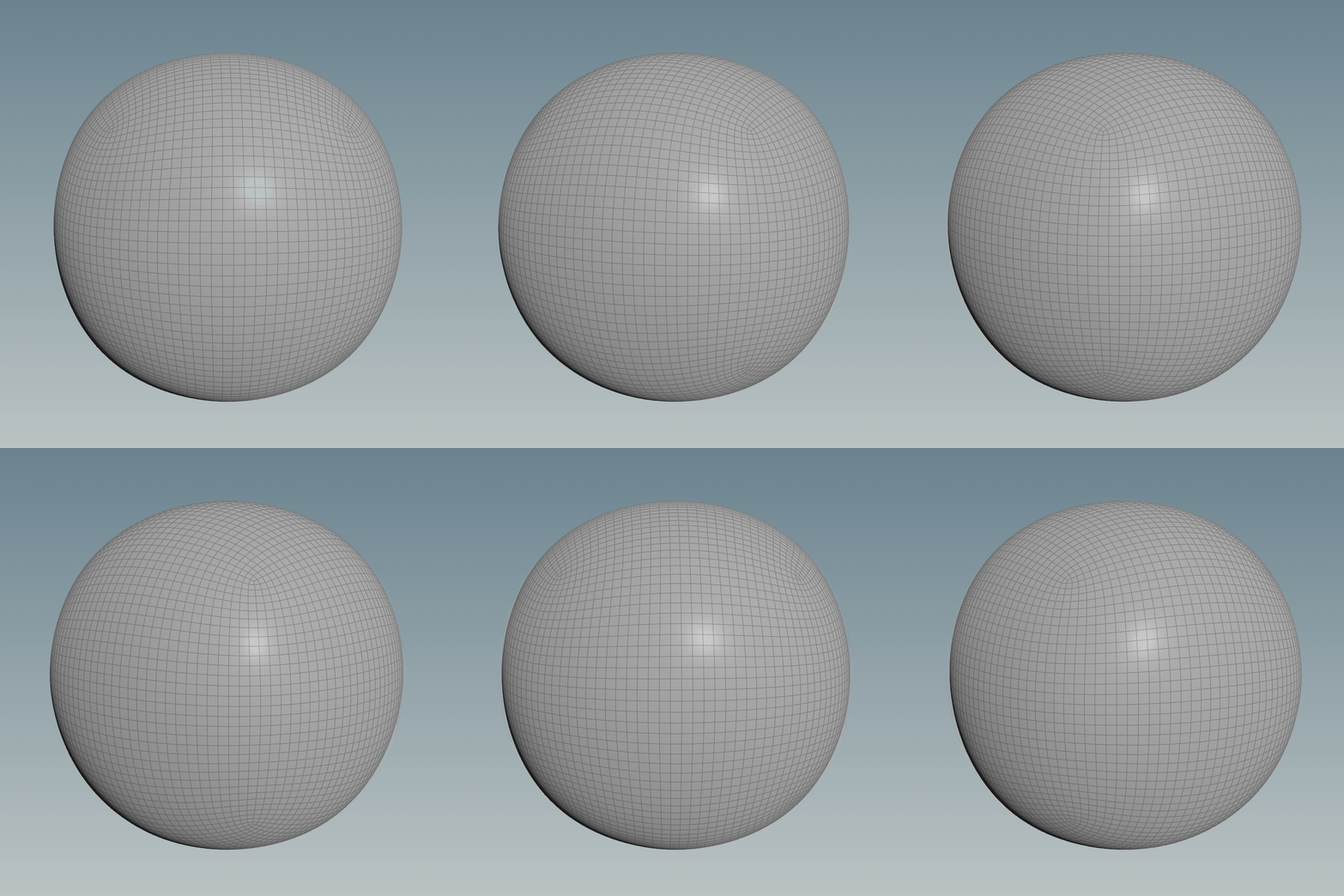
We all went down the route of subdividing a cube multiple times, but that doesn't translate to a perfect sphere:


A good workaround would be to reproject the geometry of the subdivided cube to a normal sphere, triangulated, with pinches at the poles or just having it as a Primitive.
The gif below shows a comparison animation of before and after the projection:


In Houdini it can be done using a Ray node, both the Project Ray and Minimum Distance options give similar results, you just need to make sure you scale the subdivided cube accordingly. For the minimum distance, you can get better results if the two surfaces match as close as possible, on the other hand, to make the ray option work the subdivided cube surface needs to be fully encapsulated by the sphere (or the other way around if you invert the rays' direction), but they should still be of similar size for a better result.
Below you can see the sizes of the spheres for the two different setups: 


If you can't be bothered to set it up yourself and have the Labs Tools installed, you can use the Labs Sphere Generator node, it uses this technique with Ray's Method set to Project Rays and it also generates UVs.


This helps however, the sphere you get is not completely accurate since it's dependent on the resolution and frequency of both the subdivided cube and the projection sphere used.
Here's when we turn to our friend maths and ask if it can fix our problems.
It can help us out transform a cube into a perfect sphere. We can do it using a Normalize function, applying it to the vector position of each point will cause all the points to be the same distance from the center.
This happens because it divides the vector by its own length, here's the code in VEX of three ways to achieve the same result:

@P = normalize(@P);

@P /= length(@P);

@P /= sqrt(@P.x * @P.x + @P.y * @P.y + @P.z * @P.z);


To increase the resolution of the cube you can simply use a Subdivide node with the Algorithm set to "OpenSubdiv Bilinear", but I found you can have more control in creating the cube from a Plane (Grid node in Houdini), this way you can specify exactly the resolution with a number.
You can do it using some Transform and Mirror nodes, at this stage you can also set up the UVs and assign a random colour to each face using the Connectivity node before fusing the points together.


However, the method showed above still bothers me because you can see that the vertices in the area of the original cube's corners are a lot closer to each other compared to the ones at the center of the cube's faces.


Luckily someone came up with a fancy equation that maps the cube to a sphere keeping the points spread out more evenly, almost as if you're relaxing them.
The function is:


In VEX:

float x2 = @P.x * @P.x;
float y2 = @P.y * @P.y;
float z2 = @P.z * @P.z;

@P.x = @P.x * sqrt(1 - (y2 / 2) - (z2 / 2) + (y2 * z2) / 3);
@P.y = @P.y * sqrt(1 - (z2 / 2) - (x2 / 2) + (z2 * x2) / 3);
@P.z = @P.z * sqrt(1 - (x2 / 2) - (y2 / 2) + (x2 * y2) / 3);


The gif below shows an animated comparison of the points using the two methods:

I find this animation very satisfying to look at, I can finally sleep again at night.

I hope you found this post useful, have a great rest of the day!!


Report

Smooth Stepping Curve Function - Remap Noises for stylized look - Unreal Engine

Tutorial / 07 July 2022


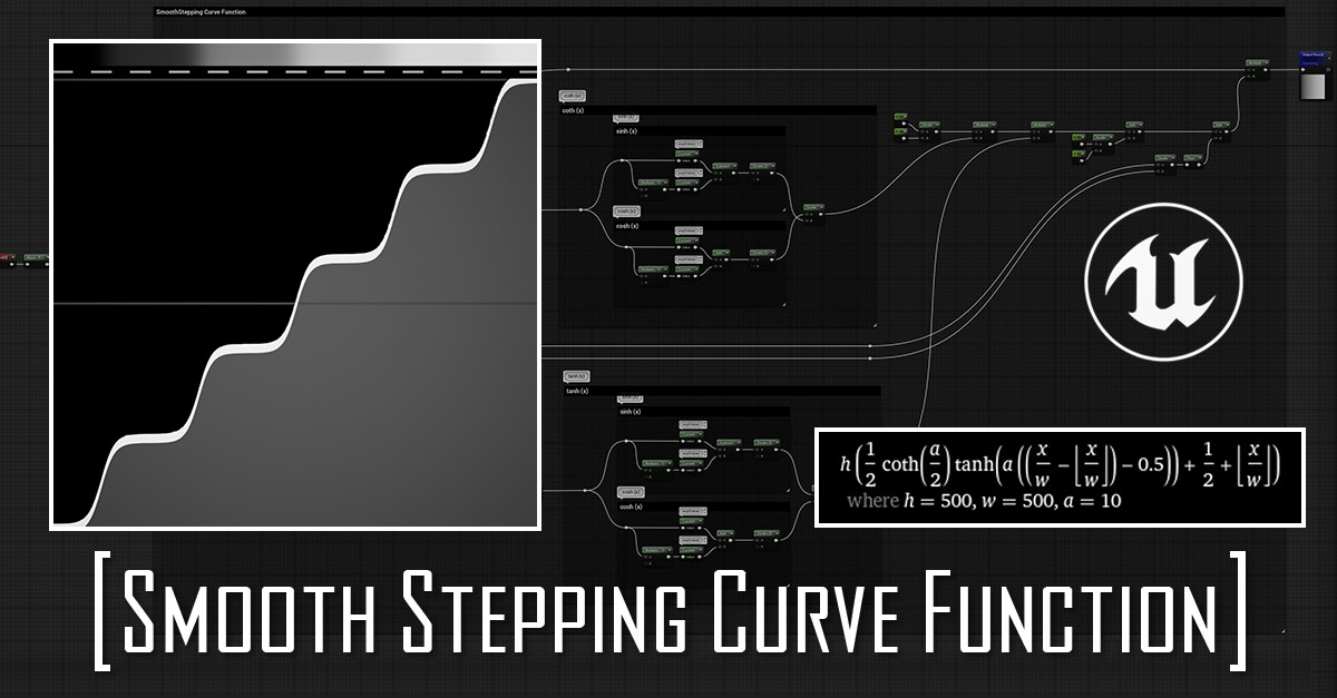
A month or so after making the Smooth Stepping Curve Function in Substance Designer, I wondered if the same could be done in Unreal Engine.
Turns out you can, but each function does add 22 instructions to the material.
I don't think I will use it much in the future and I don't really advise it for production projects, especially because in Substance Designer I found I could get better results pairing it with a blurring node (more about it here), which is not really an option in Unreal's Material Graph. For this reason, I prefer just exporting the texture directly out from Designer.

Here you can find the function applied to 3 different noises


This is the texture I used if you are interested:
Red Channel - Clouds 2
Blue Channel - Perlin
Green Channel - Crystal 2
(Substance Designer noises)


The function can be visualized and debugged by applying it to a left to right, 0-1 gradient, simply using the Red channel of the "TexCoord" node.
Then the remapped gradient can be put into a visualizer, you can find the one I made here, in there I also show the basics needed for making your own one.


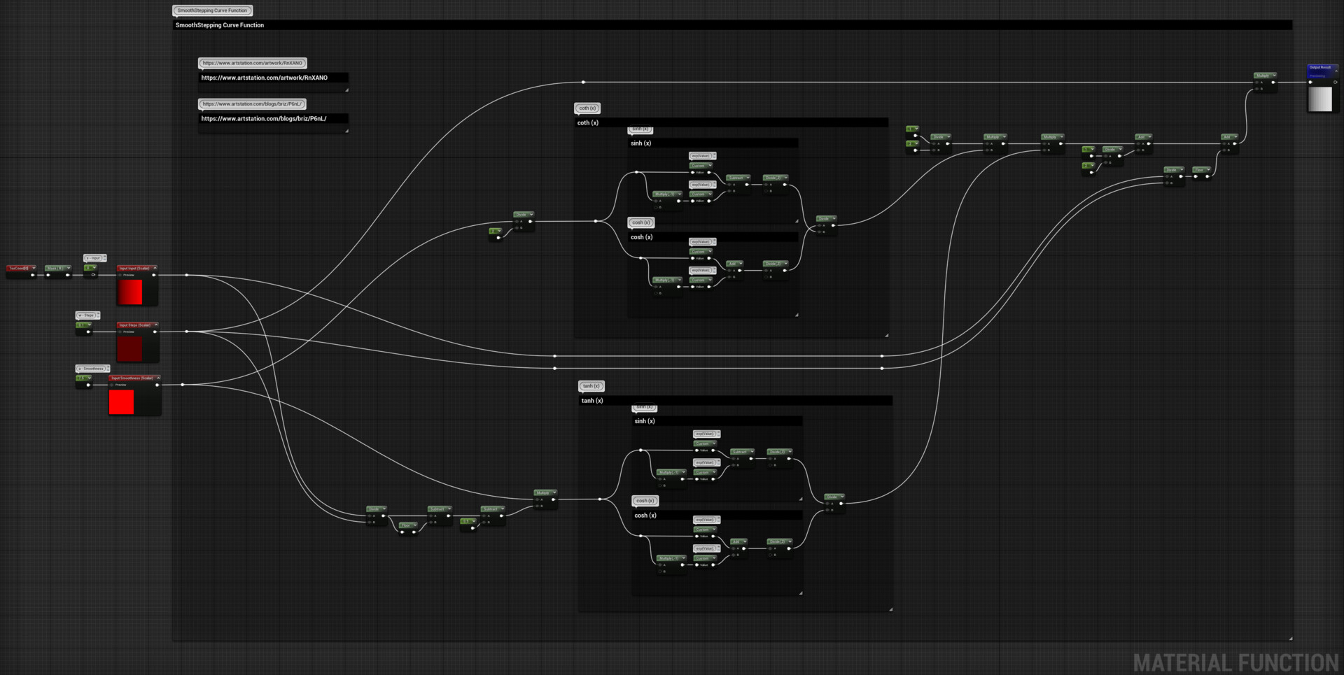
Something to mention, I don't think Unreal's Material Graph has a node for the Exponential function, so unfortunately I had to use custom nodes for it:

exp(Value);

This is the function's graph:

You can find the snippet here on Unreal's Forum.

Thanks for reading!!

Report

Linear & Smooth Step - Material & Niagara Functions

Tutorial / 30 June 2022


Intro

In this blog post, you will find a brief explanation of how these two functions work and their application, I will mainly show the setup of how they can be created as Material and Niagara functions in Unreal Engine.

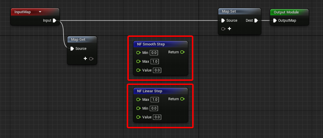
I started looking into this because I needed a Smooth Step Function to use in Niagara and I couldn't find a built-in node for it. Unreal doesn't provide it as it does for the Material Graph (or at least I couldn't find it), so I had to build my own.
Everything I've learned about how to recreate both functions came from The Art of Code's video tutorial, which I highly recommend since he explains exactly why and how they work.


The Functions

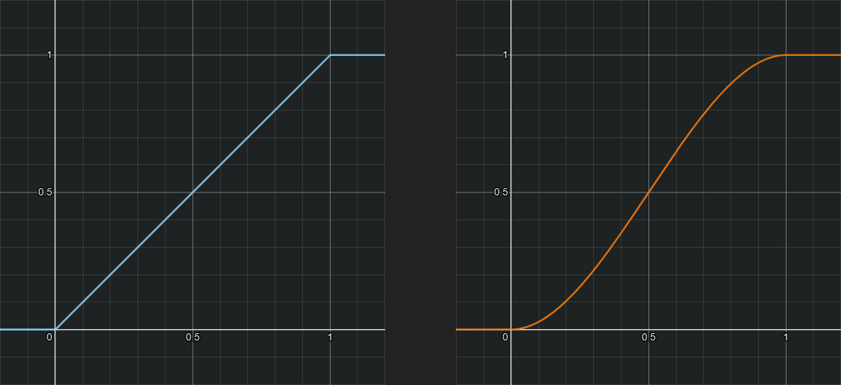
These two functions are really useful for any type of interpolation, they are very similar all around, the only difference is that
They both require an Input, and Min and Max value, which are used to clamp and control the output range.
You can find the result of both of them when Min is set to 0 and Max to 1:


Here you can find a Desmos link with the two functions, you can play around with t1 and t2 which are the Min and Max inputs respectively and I've also added a ScaleBias control to remap the output value.
c1 = Linear Step
c2 = Smooth Step
t1 = Min
t2 = Max
s = Scale
b = Bias


Material Graph

Let's start with the Material Graph.
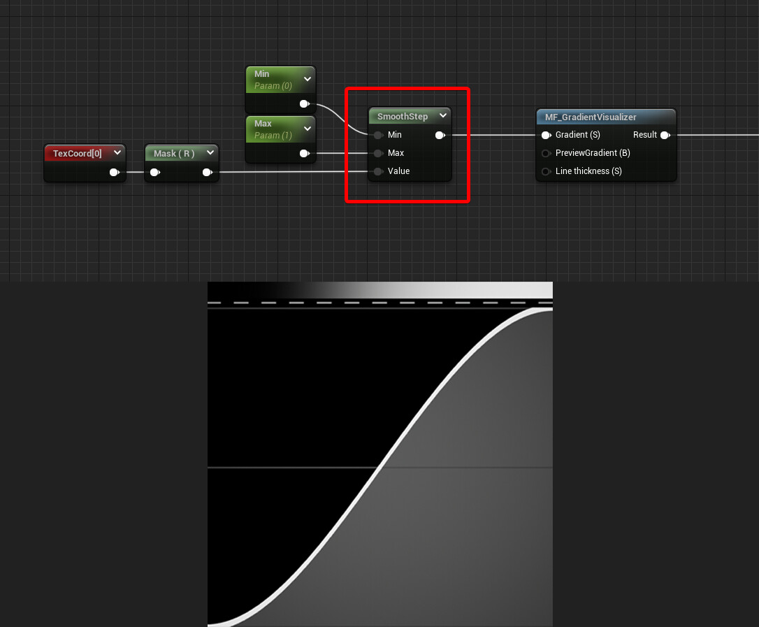
Unreal already gives provides us with a Smooth Step node with the three inputs, so we are all set.
For demonstration purposes, I'm using the UVs as my input value and a custom function to preview the result. it's the GradientVisualizer function you see in the screenshot below, if you want to learn more about it check out my previous blog post.


We can't say the same for the Linear Step function.
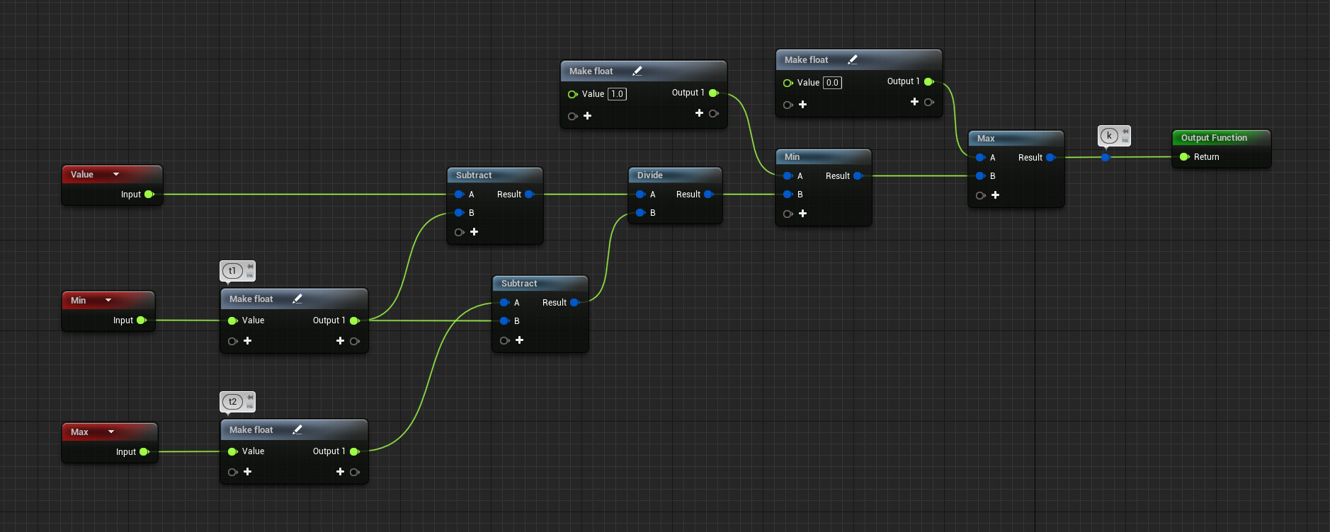
However, it's not too complicated and it can be represented as follows:

k = max(0, min(1, (x - t1) / (t2 - t1)))

Where t1 is the Min input, while t2 is the Max one.
Below you can find the setup needed to have it as a function in Unreal Engine.

snippet


This is what it looks like when you play around with the Min and Max values:


Niagara

If you've read everything before reaching this point you can probably recreate the Linear Step as Niagara Function Script without any help.
But you can find the graph below as a crosscheck:

snippet


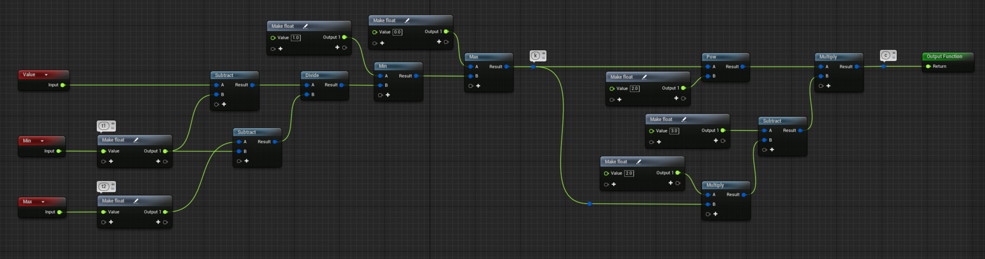
For the Smooth Step, we just need to add something to the Linear Step, basically using it to lerp between two parabolas. Again, check out The Art of Code for more information.

k = max(0, min(1, (x - t1) / (t2 - t1)))
c = k² (3 - 2k)

snippet


Once they're set up they are ready to go, to be used in any Niagara Module Script, just make sure you change the Library Visibility option of the Niagara Functions from "Unexposed" to "Exposed".


Thanks for reading and have a great rest of the day!

Report

Gradient Visualizer Material Function - Unreal Engine

General / 23 June 2022


Similar to what I've done in Substance Designer to visualize the Smooth Stepping Curve Function I made. I created a Material Function in Unreal Engine to use as a tool to visualize sine waves or any gradient I use in my materials for various FXs. If you think this could be something useful, you can find more information below.

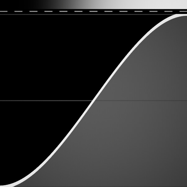
The output is divided into 2 sections: at the top, you can see a preview of the gradient input, while under it there is the curve representation.
Here you can see it visualize a Smooth Step Curve:


It's also very useful when you have an animated gradient, to easily visualize its output.
Here you can see it in action with the Triangular Wave that I showed in my previous post and with a remapped Sine Wave.

It doesn't work only with gradients, it's also helpful to visualize a uniform change of rate. For example, if you're lerping between two textures you can use the function to visualize the behavior of the alpha value.

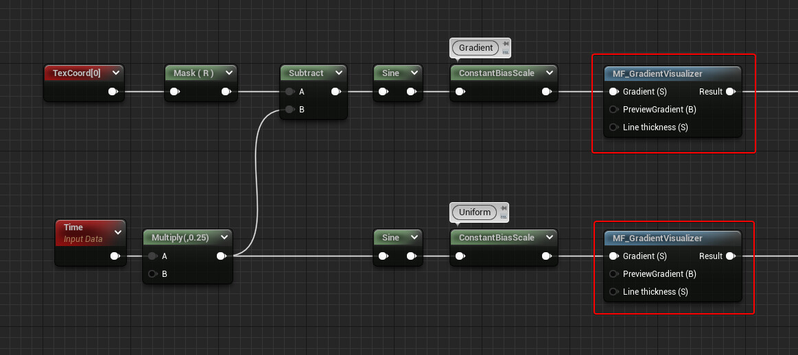
Below you can find the Material Graph and the nodes I used to have the Sine Wave as a gradient and with a uniform value:

It becomes even more useful if you're blending together multiple waves to create more complex patterns.
Here's a simple example, I'm combining two sine waves with different intensities, frequencies, and speeds:

Being able to visualize the values as curves makes it a lot easier to precisely control the output:

The way it's set up works only if the gradient is on the horizontal axis, can be easily used with the U axis of the UVs, or, if values are remapped correctly, World Position X and Y axes also work.
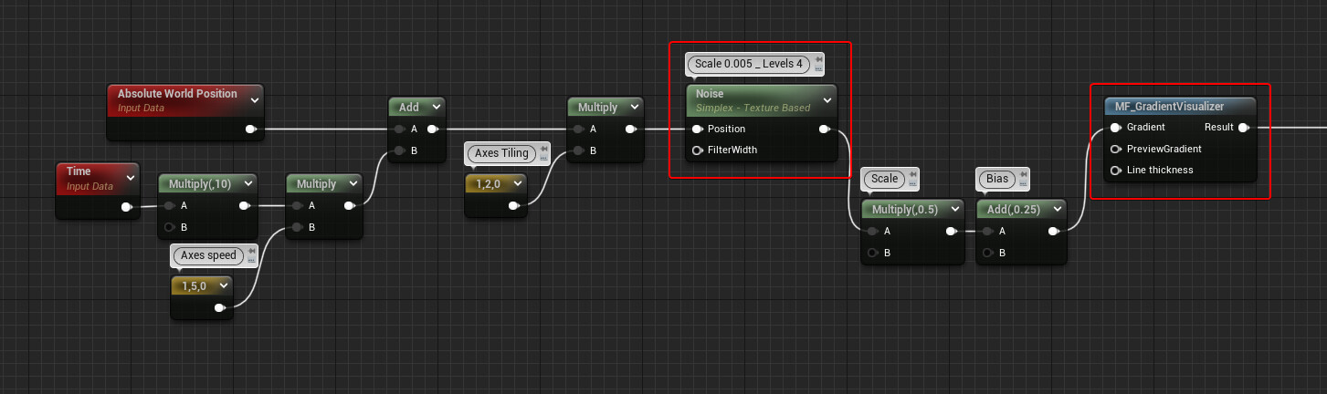
This means that with the right setup you can even visualize the Noise Node:


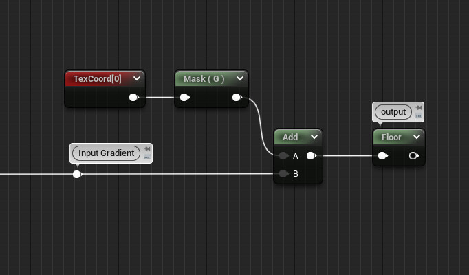
If you want to create your own, the simple setup works by adding the gradient to the Red Channel of a TexCoord node and the flooring the result.

I just made it fancier, by giving thickness to the line used for the curve, adding a preview of the gradient at the top, and some extra visual elements.
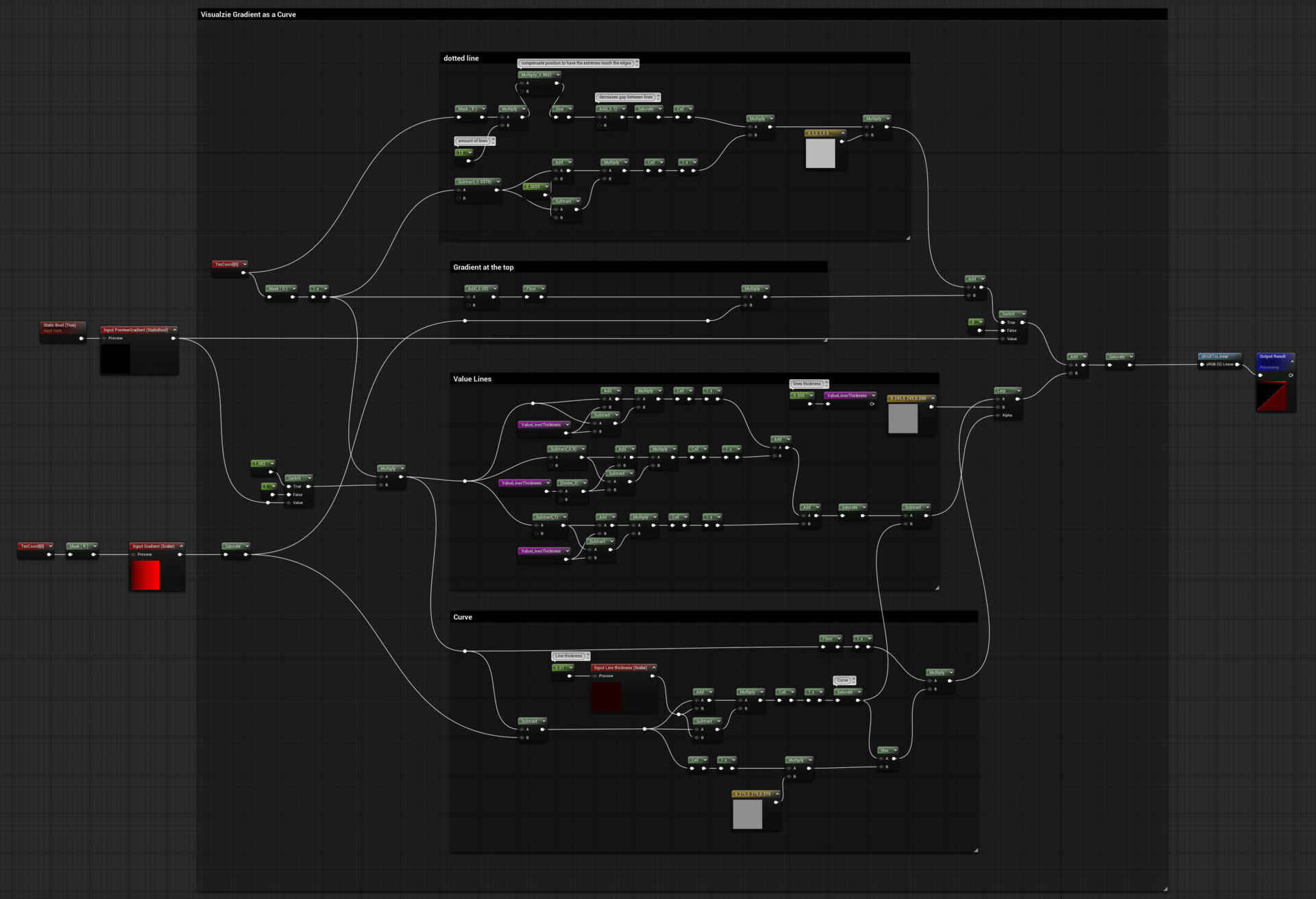
If you're interested, here's the function I made (click on the image to zoom-in).

(Snippet on Epic Developer Community)

I've also added a sRGB to Linear node to rebalance the gray colours, this way the values on the preview gradient are more balanced and precise.

Thanks for reading and I hope you found something useful in my post!!

Report

Triangle Wave Function/Modulation - Unreal Engine

Tutorial / 08 June 2022

The triangle wave function it's a cheaper alternative to a sine wave, it can be very useful as the alpha input for a lerp node when working with materials or FXs.
In some cases, it might be exactly what you're after since it allows you to blend between two inputs in a linear way.

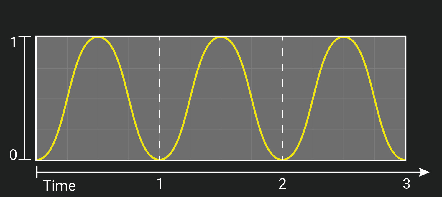
This is what a remapped 0 to 1 sine wave looks like:

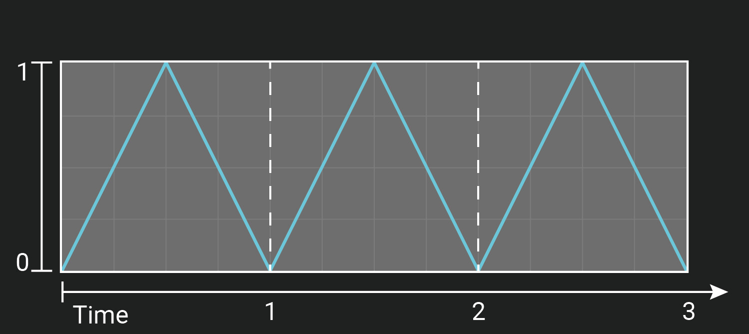
and here's the triangle wave function:


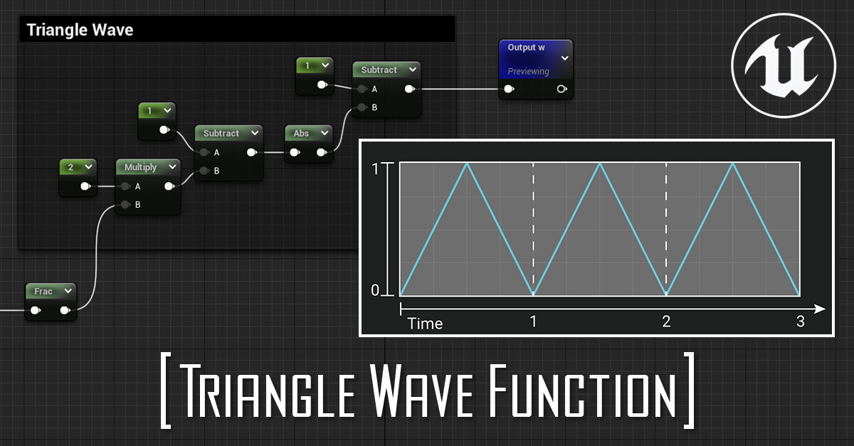
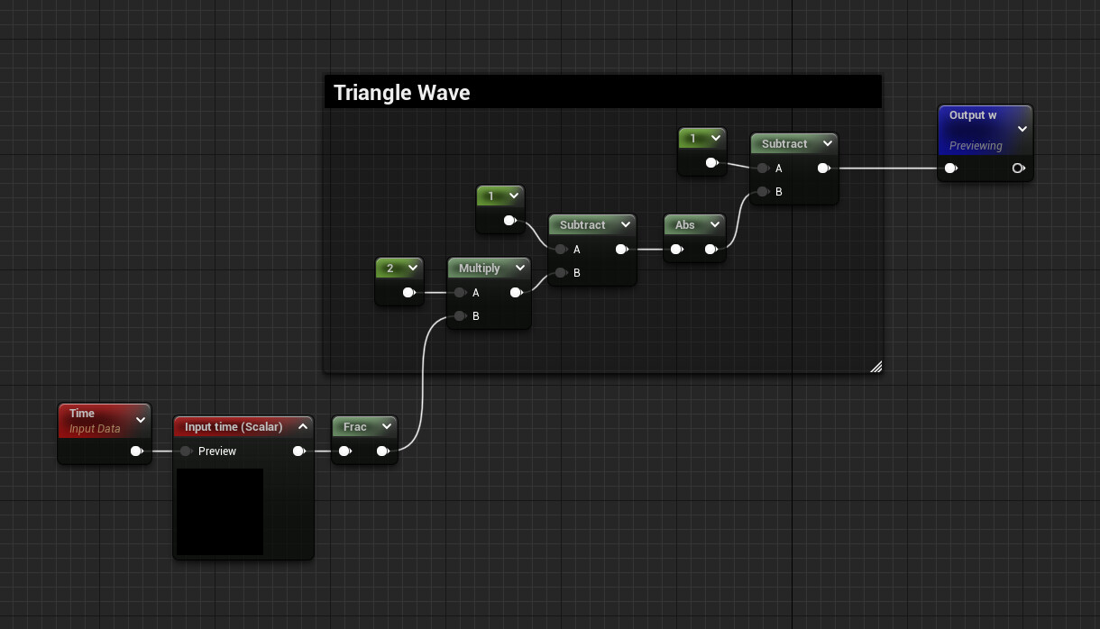
The function is

w(t) = 1 − |1 − 2t|

where | | is the absolute value.

So in code, it would be:

w = 1 - abs(1 - 2 * time);


In Unreal Engine you can create a Material Function asset, which would look like this:
(just make sure you frac time)

You can find the snippet here on Epic Developer Community.


Below you can see a comparison between the two functions, they're both lerping at the same speed between black and their respective color:
Cyan is Triangle function, Yellow is sine.
You can notice how the sine smoothly approaches the value of 0 and 1, while the triangle function ping pongs between the two values.

Here's the comparison is more evident, using the two functions to move some spheres up and down.

And again, in the gif below I'm visualizing the two functions one on top of the other.


_____   _____   _____   _____   _____   _____   _____   _____   _____   _____ 

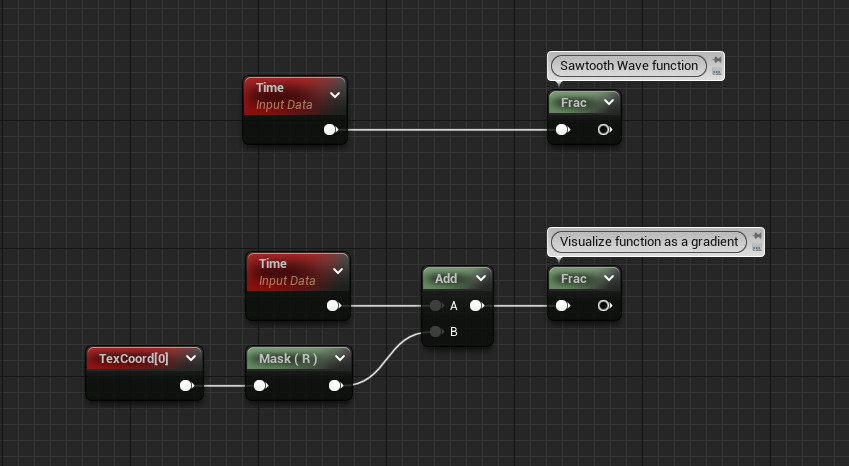
While we're on the subject, you can also easily make a Sawtooth Wave function just using time as the input of a frac node:


Report

Edit Components' Details of a Spawnable Blueprint - UE4 (Construction Script, User Friendly Parameters, Replace Materials)

General / 14 May 2022

Intro

This exploration started because I wanted to create some dynamic, but still editable, exposed variables for a spawnable blueprint. I encountered some interesting stuff that I wanted to share.
In my previous blog post, I explained the limitation of not being able to edit the details parameters of a component inside a spawnable blueprint, the changes you don't get saved because the actor is spawned "from scratch" every time. A workaround would be having the actor live in the level, but in some cases, you might not be able to set it as Possessable and it needs to be Spawnable.
The video below showcases the problem of editing the components' details of a spawnable blueprint:

In this case, the components' details can be set through the construction script, this is the only "edge case" application where I think the exploration I've done is actually useful, you can find more about the conclusion at the end of the post.

A good example of something like this would be a blueprint that is shared between different characters.
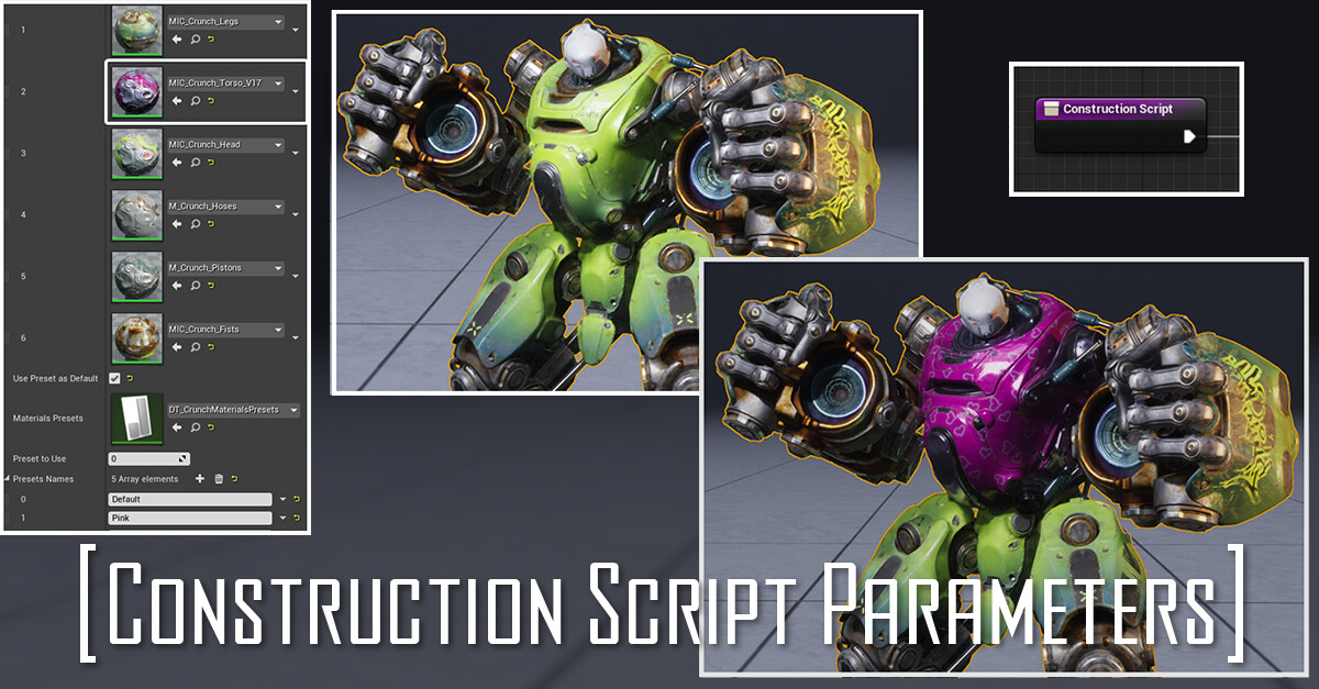
I wanted the parameters as user-friendly as possible, adding features like:
- set the array's length based on the Skeletal Mesh in use
- populate the empty slots with the Skeletal Mesh's default materials
- store the materials the user inputs
- set custom presets to use as defaults

Below I'll try to explain the various issues and challenges I came across, as well as the solutions I came up with.
Here's a demonstration of the final result:


_____      _____      _____      _____      _____      _____      _____      _____      _____      _____

Post Scriptum Discovery

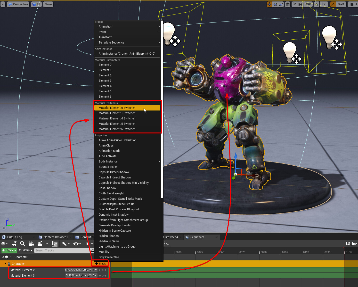
When I finished working on this entire exploration I actually found out that in Sequencer you can easily add the Skeletal Mesh component of your blueprint and override their material just using the material "Material Element" options.
Which sadly makes this exploration a bit pointless :))))

_____      _____      _____      _____      _____      _____      _____      _____      _____      _____


Dynamic but editable array

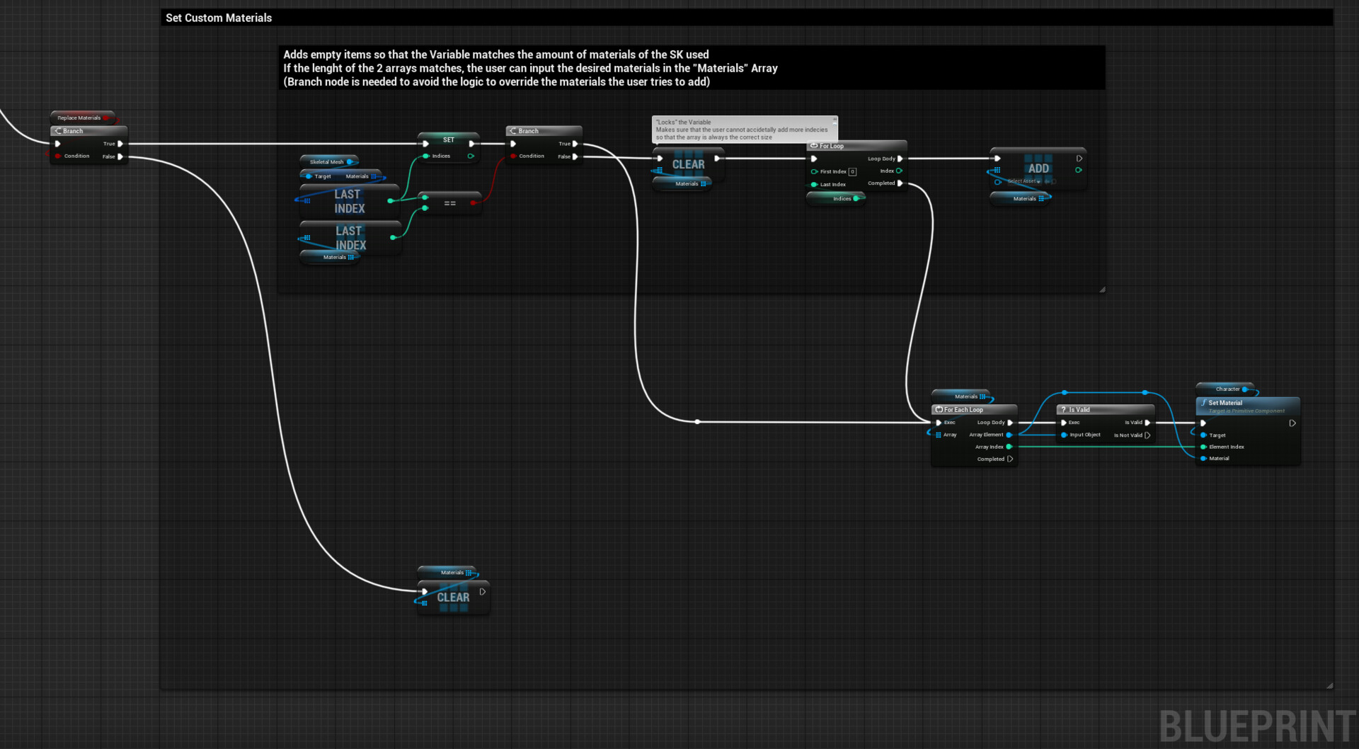
This is the main logic, a boolean "Replace Materials" updates a Material Interface array called "Materials", which is set to editable.

When set to true the array's length is compared to the number of materials the Skeletal Mesh has, if they don't match "Materials" array gets cleared and then populated empty items based on how many material slots are needed.
The branch node has also another function, when the length of the two arrays matches it stops that part of the logic to run, this way the "Materials" array doesn't get constantly reset and the user can feed the custom materials from the Details panel.  I found that this setup isn't the best when I started adding the presets feature, but I'm unaware of a better way of doing this.
After that, a "For Each Loop" sets the materials on the Skeletal Mesh Component. A "is Valid" node is used to check if the Array Element is empty, this way we can check the logic updates only the materials slot that the user defines.


Populate empty slots with SK default materials

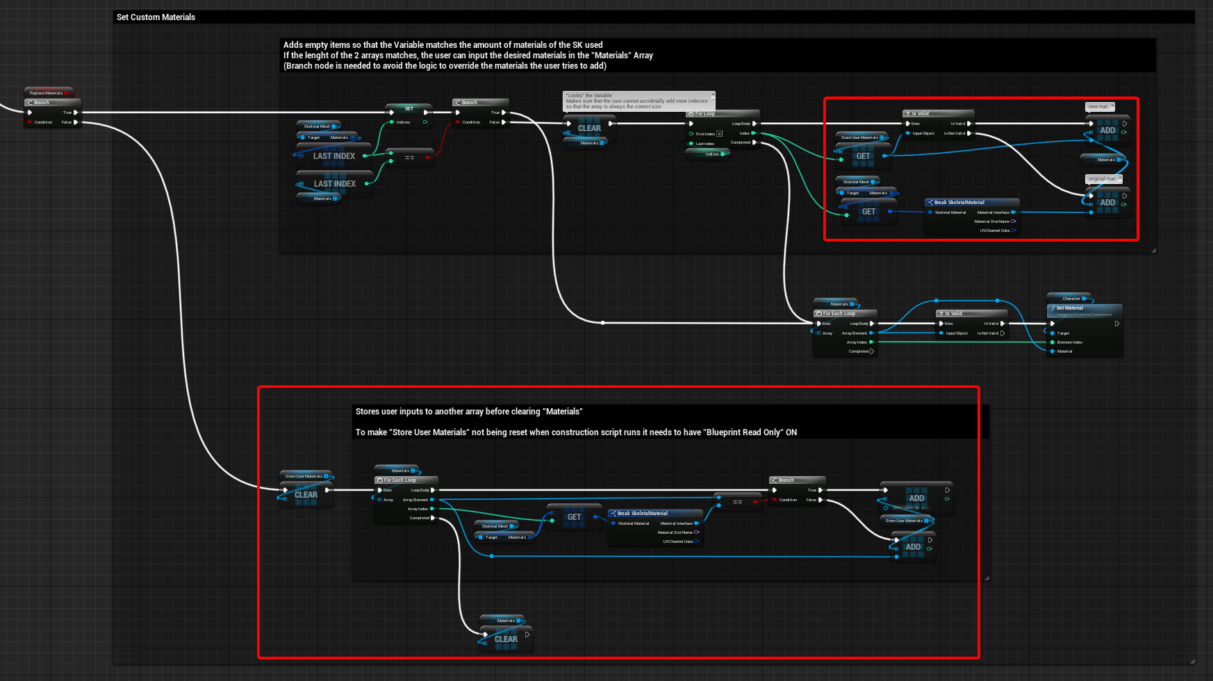
Adding this feature was pretty easy, the default materials can be set when the "Materials" array is initiated, getting them directly from the original Skeletal Mesh asset.

It gets a little bit more complicated once the next feature (store user's materials) gets added.
I found this functionality useful because this way the user can easily understand which material goes in which slot.
Unfortunately, I couldn't find a way to keep this feature once I introduced custom presets.


Store user's materials

For this feature, I had to create a new Material Interface array where I could store the user's materials.
In the image above you can see what changes I did to the graph. Extra logic was added at the initialization phase, while creating and adding the various slots it checks if "Store User Materials" array contains anything, if it does it gets added and set to the SK. Here's a closeup:


The materials the user inputs get stored once the boolean "Replace Materials" is turned to false, here's a closeup of the logic:

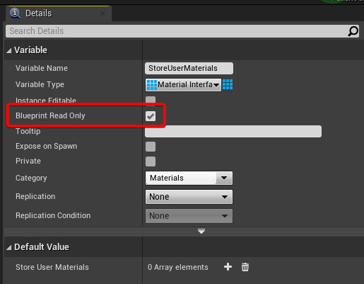
To make the variable array "Store User Materials" work, I had to turn on "Blueprint Read Only".


This way we are a little bit exploiting how arrays work in Unreal:
to store the user's materials we need to stop the blueprint to reset the array every time the construction script runs, which is possible by setting "Blueprint Read Only" to true.
However, this is when I realized that this way you can't set directly the variable with a "Set" node, but even if the variable is "Read Only" we can still clear it and add items, even if theoretically you shouldn't be allowed to.
Moreover, this made me notice that the same applies if "Instance Editable" is turned on.
Therefore this whole exploration was made possible by this exploit.
I believe this has something to do about mutable and immutable variables and how arrays are implemented in Unreal Engine.


Set custom presets as default

I initially tried to have the presets as structs, but it wasn't the right choice since I would have needed separate Structs for each preset and tI couldn't find an easy way to dynamically swap between them the blueprint's logic.
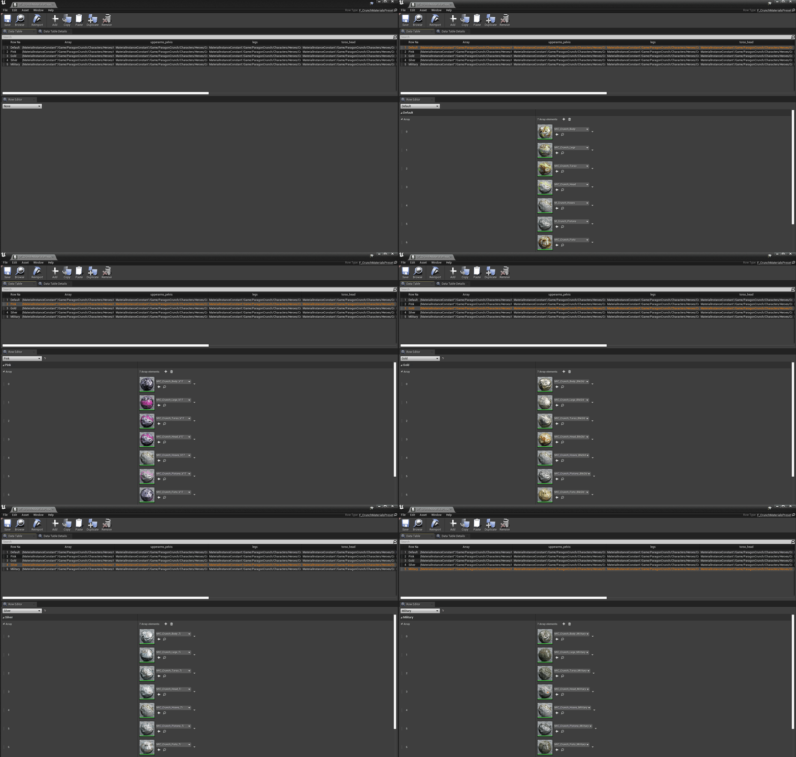
Data tables, in this case, are a better solution since they are more flexible, they can't be set at runtime so they require some initial setup.

Data Tables are generated from a Struct asset, to make it work with different characters the Struct needs to contain an Array variable since the number of slot materials is not defined. However, the setup needs to be only for one specific character I would use a Material Variable for each slot so that a name can be added to match the slot name used on the Skeletal Mesh.

If you want to add the names of the slots, you could probably have another array of Name variables, so that you can store that information as well. This way you could actually re-arrange the order of the slots and set the materials on the Skeletal Mesh using the "Set Material by Name", this way you don't have to rely on the array order.


Here's the final graph: (Click to open in full size)

Adding the presets and keeping the previous features was quite confusing, the major issue was keeping both the user inputs materials and populating the slots with the preset's default materials. To have both features I would need to check if a new presets has been set and when that happens re-initialize the "Materials" array, which could be done only by storing the previous preset number in an integer variable so that it can be compared with the new one. The problem is that the variable gets reset every time the construction script runs making this impossible, the variable wouldn't get reset if "Instance Editable" or "Blueprint Read Only" were active, but in this case, the "Set" node would be unavailable, it's not like the arrays where I could still use "Clear" and "Add".


Conclusion

I didn't really have a solid plan when I started this exploration, I just kept saying "oh it would be nice if you could also have this", every time I completed a feature. I should have planned out more what I wanted to achieve, this might have helped with structuring the logic that would have allowed implementing the features in a smarter way. Maybe it could have even been a separate plugin, avoiding working in the construction script, avoiding all the limitations and complications I encountered when trying to make all the features work together, which was really hard to manage.
I, unfortunately, can't think of many cases where what I've done could actually be useful. Especially because it was made possible only by the fact that you can still clear and add items to a Read-Only array.
Having an array that automatically sets its length was a nice addition and also, it was the first time I used data tables, they are really powerful and I definitely would like to explore more in the future. 

I hope someone found this interesting!
The assets used for this article are from Paragon's free content on Unreal Engine's Marketplace.

Report

Sequencer and Blueprints tips - UE4

Tutorial / 05 March 2022

I wanted to collect together and share some tips I think would be useful for anyone that needs to work with Sequencer in Unreal Engine. It's really just a collection of random things I learned working on shot-based projects that I wish I knew beforehand.
This post might be useful for any beginner or anyone
I will be covering how you can expose, have control and update blueprint variables in sequencer, as well as some extra considerations on that, I will also show some limitations I found about spawnable actors, and some tips on how you can animate cameras and how to make that process easier for yourself.
Here's a preview of what I will be creating, but there is more stuff I'll show that is not included:
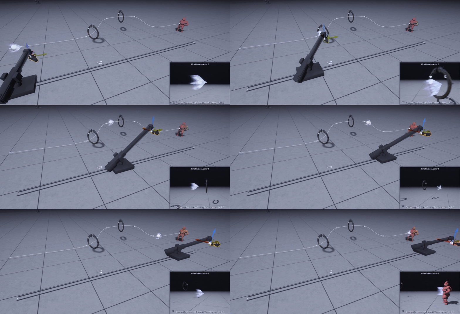

  1. Edit and update Blueprints' variables in Sequencer
  2. Attach Actors to Blueprint's component
  3. Cine Camera, Camera RigCrane and Rail combo
  4. Multiple viewport workflow tip
  5. Spawnable Cameras in Camera Cuts gotcha
  6. Spawnable Blueprint, edit Components' details

________________________________________

Edit and update Blueprints' variables in Sequencer

In the example, I'm creating I want to animate an actor along a spline.
To do that I made a blueprint where a Spline is the root and a Scene component, that I called "Mount", is attached to it. The idea is to use the spline to define the path and animate the scene component in sequencer updating its location, making it ride the spline.
I also added a sphere to Mount, so that I can visualize and debug its current location.

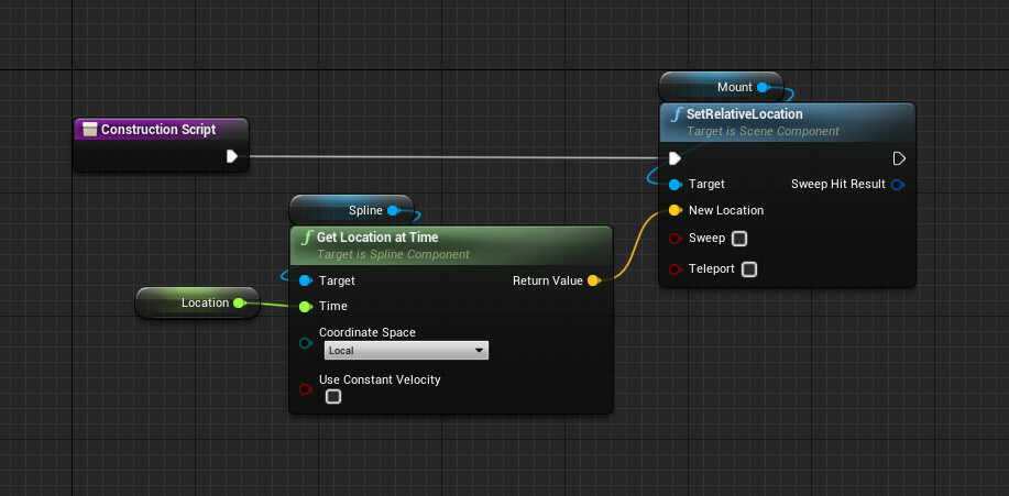
To update Mount's location using the spline I just set its relative location using a "Get Location at Time" node in the construction script and exposed time using a float variable, this way I have a normalized 0-1 control.
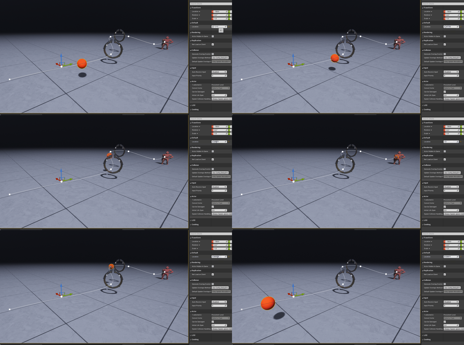
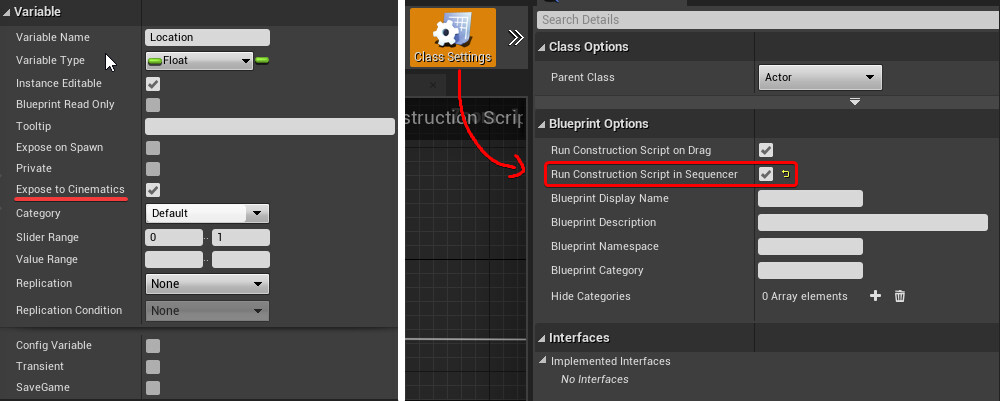
To make the variable editable in Sequencer you need to turn on "Expose to Cinematics".
However, doing only even if you add keyframes to the exposed variable in Sequencer, nothing will actually happen in your viewport because the logic used to update the location of Mount runs on the construction script. Luckily there is a way to re-run the construction script while scrubbing through the timeline, just go under "Class Settings" and turn on "Run Construction Script in Sequencer".

Now Mount moves along the spline in the viewport, but if we drag the Sequence in the level, set it to autoplay and simulate, the Sequence will start to play but nothing will happens. This is because Mount's location gets updated only in the construction script, but to have it move at runtime it needs to be updated on tick.
So what I did was to collapse the logic to a function and have it run both in the Construction Script and on EventTick.

I'm not sure if this is the best way approach, if anyone has a smarter way of integrating blueprints with sequencers please reach out!


________________________________________

Attach Actors to Blueprint's Component

Now that the Spline blueprint is set up, any actor can be attached to the blueprint component Mount directly through sequencer.
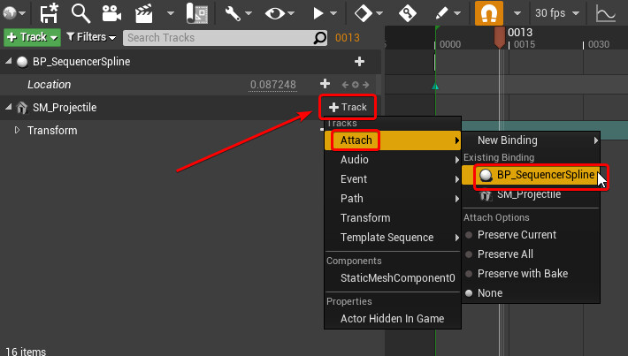
For this example I'm attaching a simple Static Mesh, just reference it in the Sequencer click on add Track, go under the Attach menu and choose the desired blueprint.

Then right-click on the attachment track of the Static Mesh, select Properties, and fill up "Attach Component Name" with the name of the desired component, in this case it will be "Mount". Here you can also change the attachment transforms rules if needed, I found setting "Attachment Location Rule" to "Snap to Target" helped get consistent results.

After that's done the Static Mesh should move along the spline while playing the Sequence. However, you probably noticed that while scrubbing back and forth in the timeline it looks like the Static Mesh is offset by one frame compared to the debug sphere.
In the gif below I've attached a green cube, you can see that in the first frame the location of the two meshes matches perfectly but when I start moving in the timeline, at the first frame the cube remains still and then follows the red debug sphere with a delay of one frame.

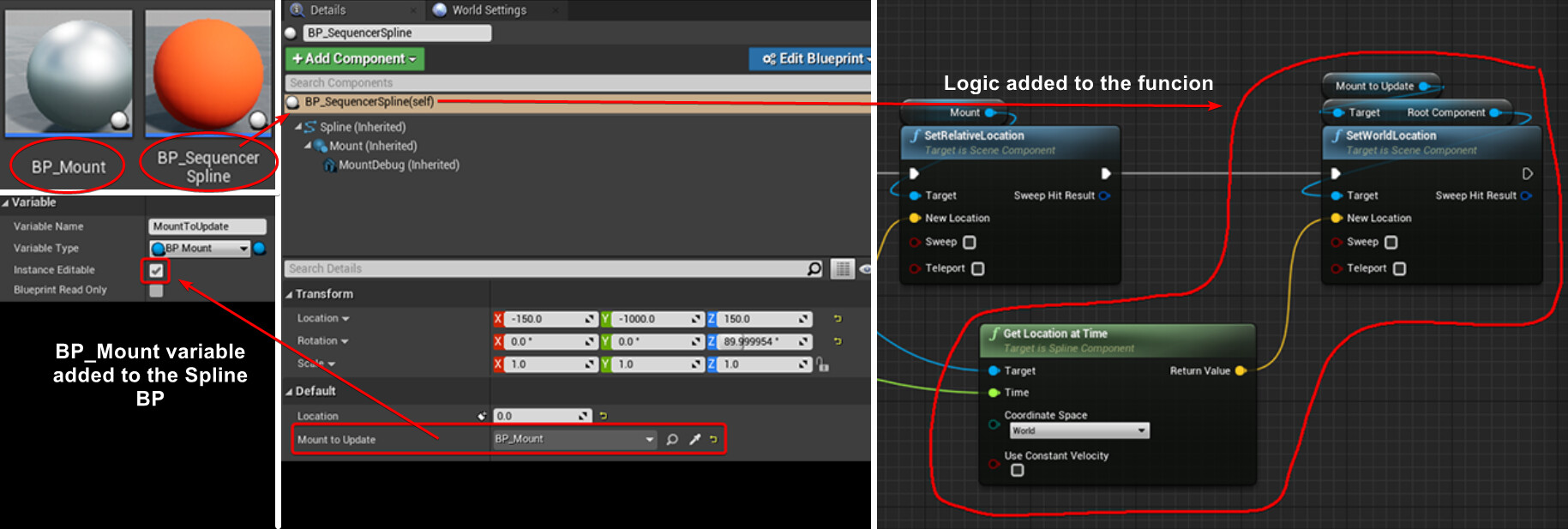
I'm not sure why this happens, but a workaround I found was to avoid attaching the static mesh to the Mount BP_Spline component and instead separate Mount from the Spline Blueprint.
The new BP_Mount is referenced by BP_Spline, so that the mount location can still be updated. Then you can attach the Static Mesh that needs to follow the spline directly to BP_Mount.

The gif below shows the result in the viewport. The silver sphere is for debugging the location of BP_Mount, it has a little bit of offset in the X-axis to visualize it better. I've also duplicated the green box and attached it to BP_Mount directly to compare the two final results
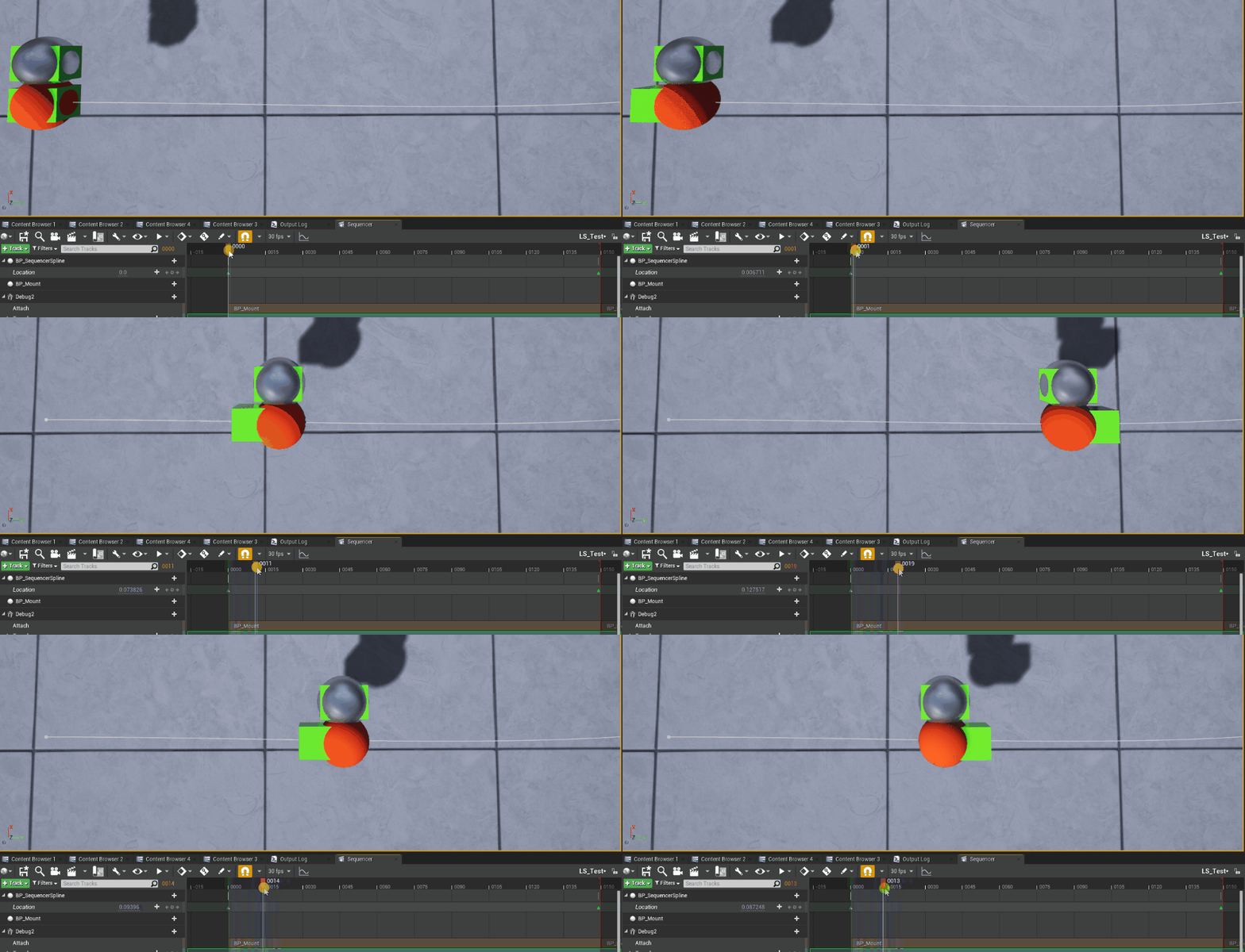

The test renders results are quite interesting tho, below you can see the render done using the normal sequencer renderer, the Static Mesh attached to BP_Spline's Mount component is completely broken and doesn't move.

However, when using Movie Render Queue both alternatives give the same exact result.
So if you're using MRQ this extra step of having the Mount as a separate Blueprint is only useful to review the correct location in the viewport.

Again if anyone knows more about this issue please reach out!


________________________________________

Cine Camera, Camera Rig Crane and Rail combo

I'm not going do to an in-depth dive regarding this, you probably are already aware of the Camera Rig Crane and Rail, but remember that they can be used together, attaching a Cine Camera to a Crane and then move the Crane along the Rail. You can get rapidly excellent results with this method since it allows you to control the location of the camera very easily, as well as keep full control over its relative rotation.
For more information check out the documentation of both the Rail and the Crane.

You could argue I could have used the Rail Actor to animate the projectile along a spline, and you would be right.
The reason why I made a custom blueprint it's because that gives you a starting point to create something more complex, also you might have a spline system already in your project. In the past, I found this technique useful because I could use a Catmull–Rom spline I made.

You can also attach the crane to the spline used by the Projectile, to have a camera that follows the action.

I mentioned I could have used the Rail actor to animate the projectile, the same applies for the Crane, static meshes can be attached to it as well. Here's a spooky floating head that I quickly animated using the Crane, and try to overlook the fact that I'm not a good animator.


________________________________________

Multiple viewports workflow tip

When working on Sequencer's animations I prefer working with 2 viewports so that I can freely navigate the 3D space in one of them, while having the other one always locked to the Cine Camera so that I can always check the final result.
The best way to do that is by turning off "Allow Cinematic Control" on one of the viewports in the viewport's options, this way when clicking on "Lock viewport to Camera" in Sequencer's Camera Track only one of them will be affected.
Unfortunately, it needs to be done every time the engine is restarted.


________________________________________

Spawnable Cameras in Camera Cuts gotcha

This is a weird one and it only applies if the camera is Spawnable and not when they are Possessable.
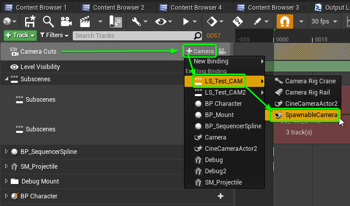
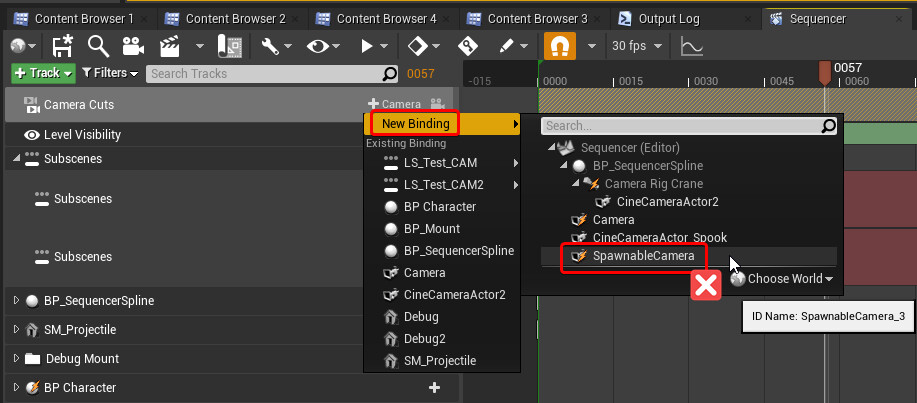
When working with spawnable cameras make sure you add them to the Camera Cuts referencing them from the Sequence and not the World Outliner, the two images below show the right way of doing it:


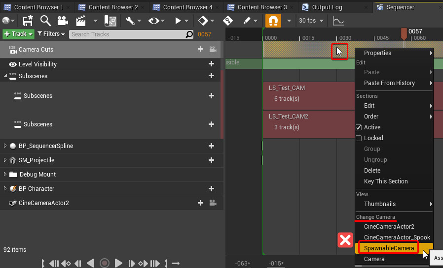
Avoid selecting them using "New Binding" when clicking on the + button, or selecting them from "Change Camera" section if you are replacing the existing one by right-clicking on the track.
The two images below show the wrong way of doing it:

This is especially a problem if the camera is not in the same Sequence of the Camera Cut, but it's instead in a sublevel. If done in the wrong way the Sequence will look for the camera in the World Outline and the reference will be lost the moment the camera is despawned.
You can notice straight away if you are doing it right or wrong, because if you are doing it wrong a reference to the camera gets added.
Below you can see an example of the issue.


________________________________________

Spawnable Blueprint, edit Components' details

I encountered this limitation when I had a spawnable blueprint with a character inside it and I needed to replace its assigned materials, the changes didn't save. This applies to any parameter in the Details tab, not only materials.
The video below showcases the problem:

I saw that right-clicking the actor there is a "Save Default State" option, but it doesn't seem to do anything and I couldn't find more information about it.


There are two solutions to this problem, you can either just covert the actor to Possessable so that it lives in the level and any changes done in the Details panel get saved in there. Or, if it needs to remain Spawnable, the materials can be set in Construction Script.

________________________________________

This brings me to another exploration I've done, where I tried to create a dynamic, but still editable, array of materials. Making the parameters as user-friendly as possible, adding features like:
- set the array's length based on the Skeletal Mesh in use
- populate the empty slots with the Skeletal Mesh's default materials
- store the materials the user inputs
- set custom presets to use as defaults
However, I've covered that in another blog post.

I hope there is someone that found this useful!
The assets used for this article are from Paragon's free content on Unreal Engine's Marketplace.
Report

Fall Guys' Map Loading Screen BG - How to make Circle Shapes and Expanding Rings - UE4

Tutorial / 31 August 2020

I played Fall Guys recently (who didn't?), I often die in the first rounds so I find myself staring at the loading screen for ages waiting for the other players. Soon enough I started wondering if I could recreate it in a shader without using textures..
Well, turns out I could and it's quite simple! I decided to share how I've made it since it's very easy and making circle shapes can be extremely useful for many different shaders.
So with this post, I'll try to quickly show you an easy way to make circles and expanding rings in UE4's graph editor.


_____ _____ _____ _____ _____

Radial Gradient

The core logic is very simple, you can get a radial gradient finding the distance between all the UV coordinates and an arbitrary vector2 value, which will be the center point of the gradient.


I don't really like working with vector2 nodes, especially if I want to expose the values..
This is what I would set up instead:

Just a personal preference, I'm offsetting the Texture Coordinates so that I can position the circle at the center using the values 0,0


Circle Shape

Now we can use a step function to generate the circle and control its size.
You could use a custom node and write your HLSL function:
return step(x,y);

However, if possible, is better to avoid custom nodes. In this case we can since we are not doing anything fancy and we can achieve the same result in different ways.
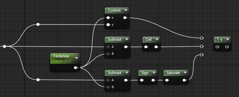
You can control the size of the circle using a float, subtract this value from the gradient we previously made and ceil the result or use the sign node instead, but if go for the second option remember to add a saturate node as well since the sign node returns negative values!
OneMinus the result to invert it.


If want to make the edges of the circle softer you can use a SmoothStep function instead, Unreal already has a node ready for us!
Make a scalar parameter for the step size, then subtract and add it to the Circle Size to get the Min and Max values for the SmoothStep node respectively.
This way when you change the Step Size the circle's edges will get smoother uniformly, inside and outside the circle.


Expanding Rings

If you just wanted to make a circle then you're done, however it doesn't move... Boooring!
It really depends on what you're after, you could animate any of the parameters exposed: its position, radius or even the smooth step size!

Add, or subtract, and then frac Time just before the step or smooth step we made previously.

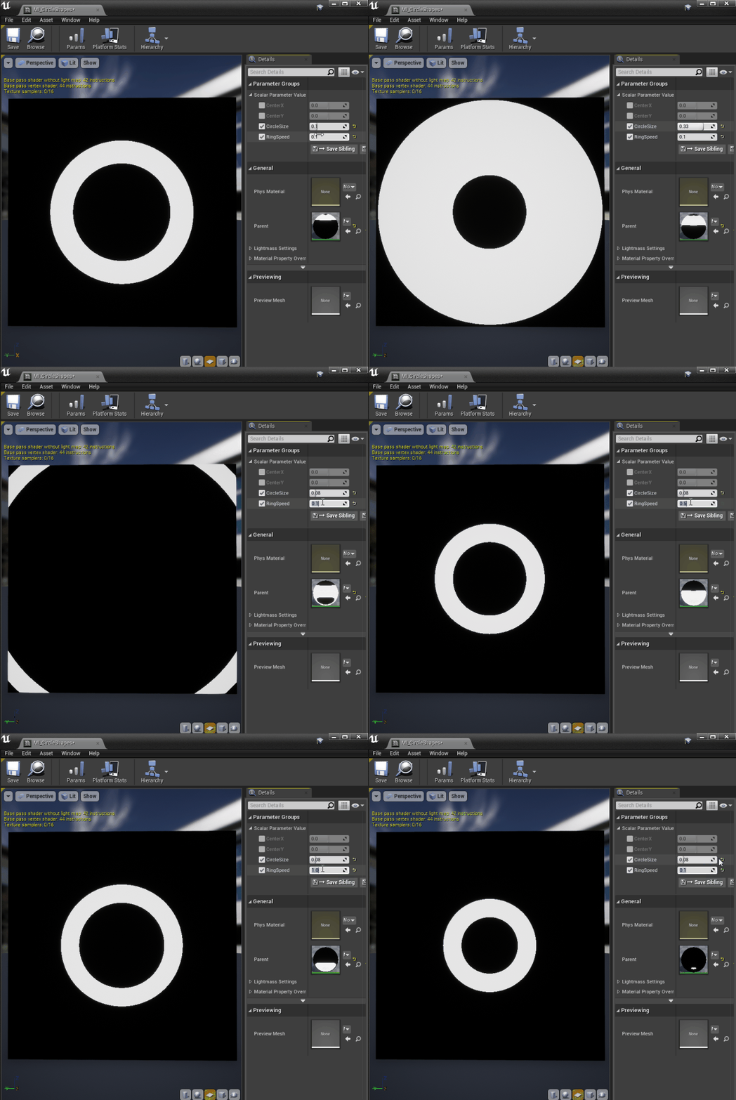
This will transform the circle in an expanding ring, its thickness is still controlled by the scalar parameter we previously made for the size of the circle and multiplying Time you can speed up, slow down, or even reverse the animation.


It will work fine with the step logic, but not with the smooth step one since only one of the edges will be smoothed out:

If you want to have them both smoothed you'll have to add another SmoothStep node, unfortunately.
You can think of the ring as 2 circles one inside the other, so you'll need SmoothStep for the outer and one for the inner circle.


_____ _____ _____ _____ _____

Fall Guys' Map Loading Screen BG

Now you know everything you need to recreate a loading screen like Fall Guy's one!


An overview of the shader I made:

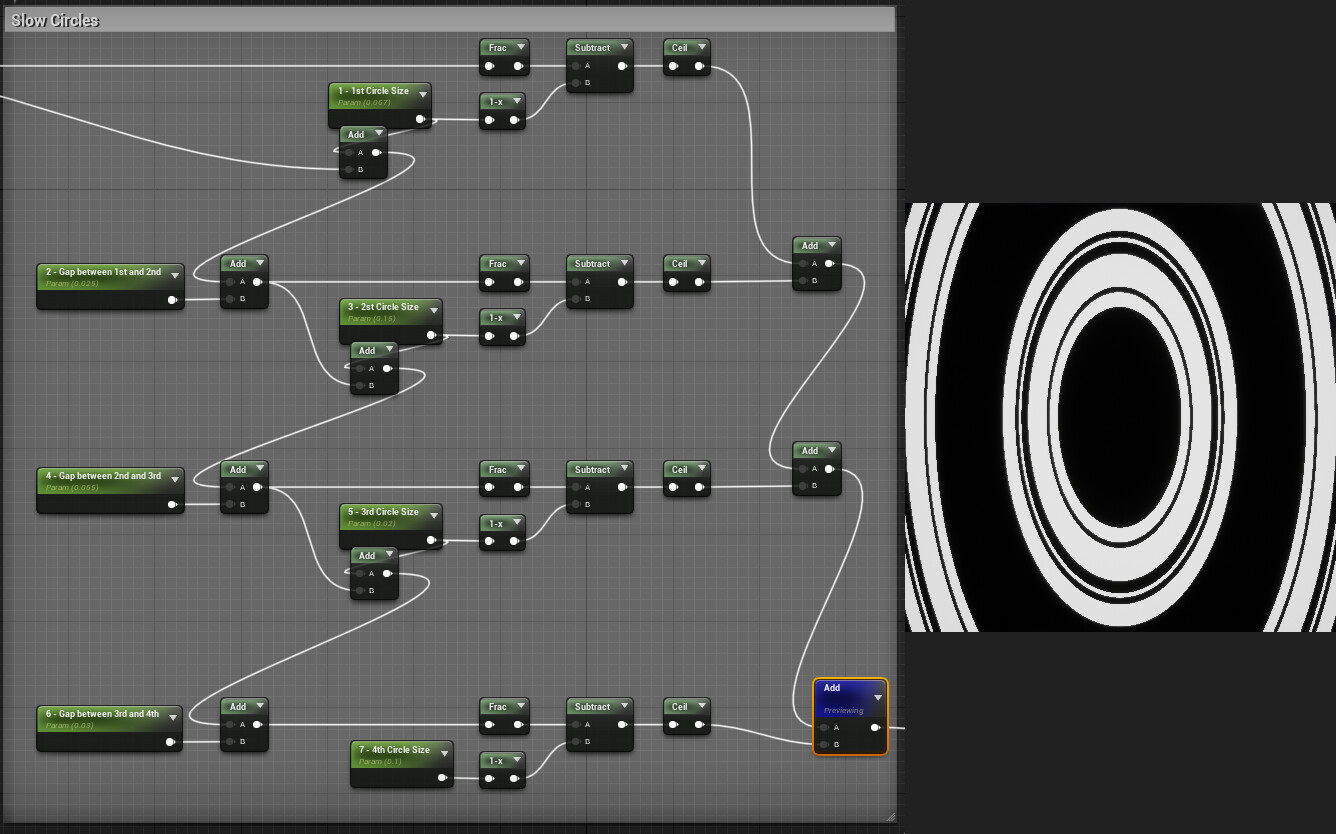
This is the graph:


Radial Gradient
Starting with a radial gradient.
The only thing to mention here is that I'm scaling the UVs and the plane mesh I'm using to test to get a rectangle instead of a square.


Expanding Animation

Then I'm subtracting Time to animate the rings that I'm going to make.
There are two sets of rings, one set is faster than the other, so I'm multiplying Time by 1.5


Rings - First Set
In the first set contains 4 rings of different size, the gap between them is also different.
I wanted to make the shader somewhat procedural, so I had to set up a system that scaled everything accordingly if I was changing the thickness of a ring or the size of a gap.


Rings - Second Set
The second set only has one ring, quite straight forward.


Colour
Then I use the 2 rings sets as masks and add some colour with lerp nodes.
I also made a linear gradient mask using the Green channel of the Texture Coordinate.


I straight up copied Fall Guys, but with these techniques you can make a lot of different cool effects!!

Thank you for reading all the way here, I hope it was somewhat interesting!
  

Report

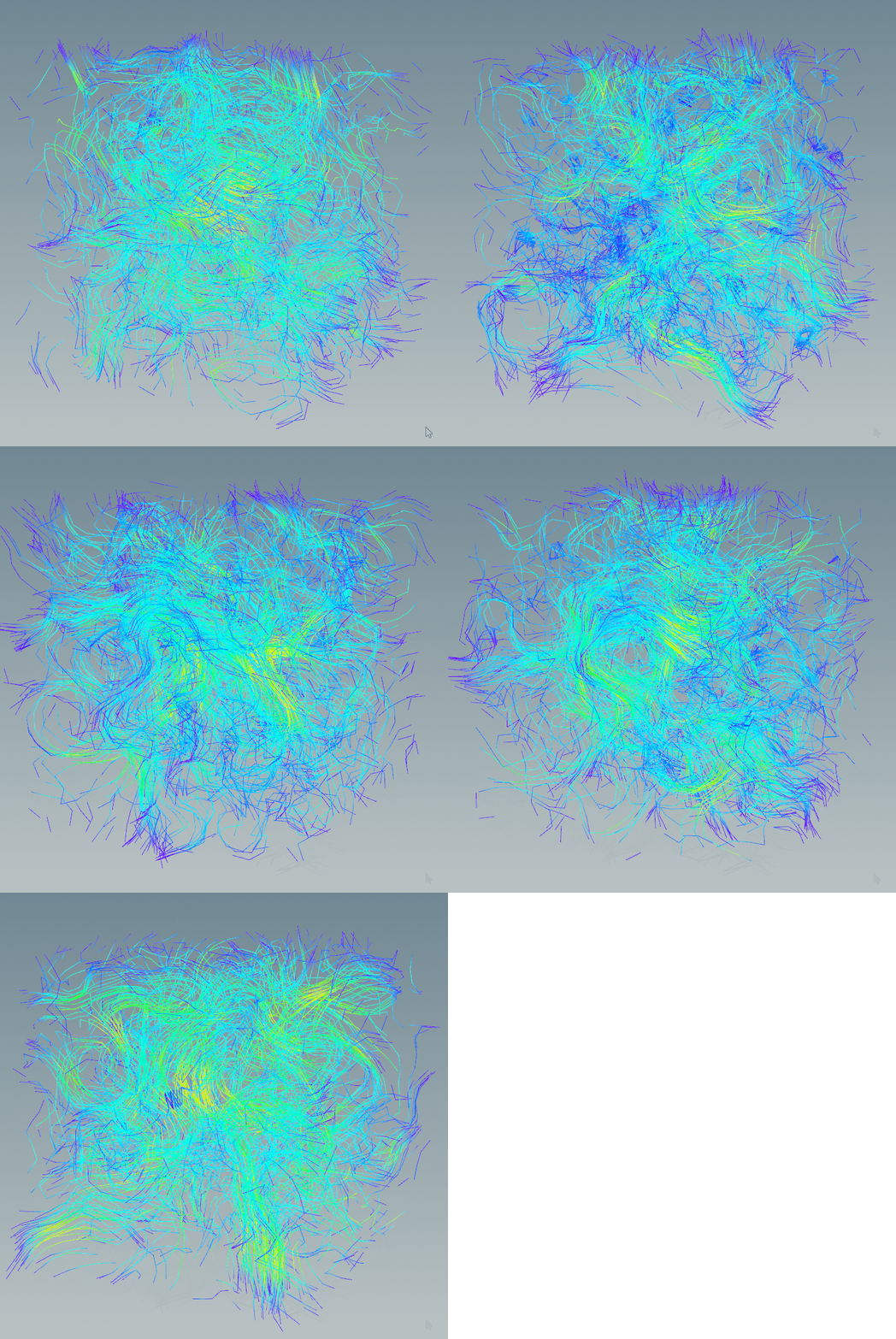
Generate a Vector Field Noise for UE4 using Houdini

Tutorial / 08 March 2020


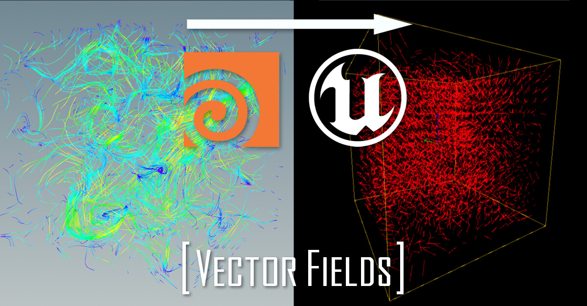
I recently started experimenting with vector fields and I thought this might be useful for anyone that wants to do the same.
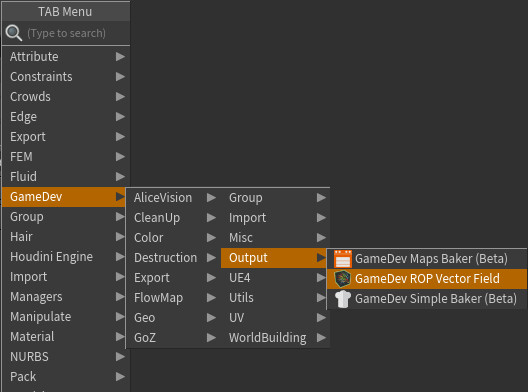
I'll show you a couple of ways to generate them in Houdini, both ways make use of the GameDev ROP Vector Field node, so make sure you have the Game Development Toolset!
This node allows you to export a .fga file which is supported by Unreal Engine.


Vector Field from Points

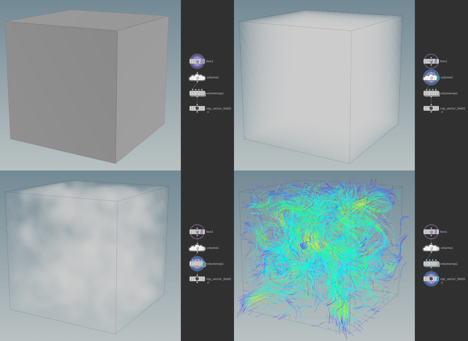
To generate a Vector Field using points any type of geometry can be used, I'm using a box to keep things simple.
Then the geometry needs to be converted to a volume so that you can scatter points inside it, this can be achieved using either a Volume node or an IsoOffset one.

After that, you can apply noise to the points using an Attribute Noise node, remember the attribute name you are using since it's important for the next step, also make sure you remap the values between -1 and 1 if you want the noise to have a uniform look.
Feel free to play around with the Noise Type and the Element Size parameters.


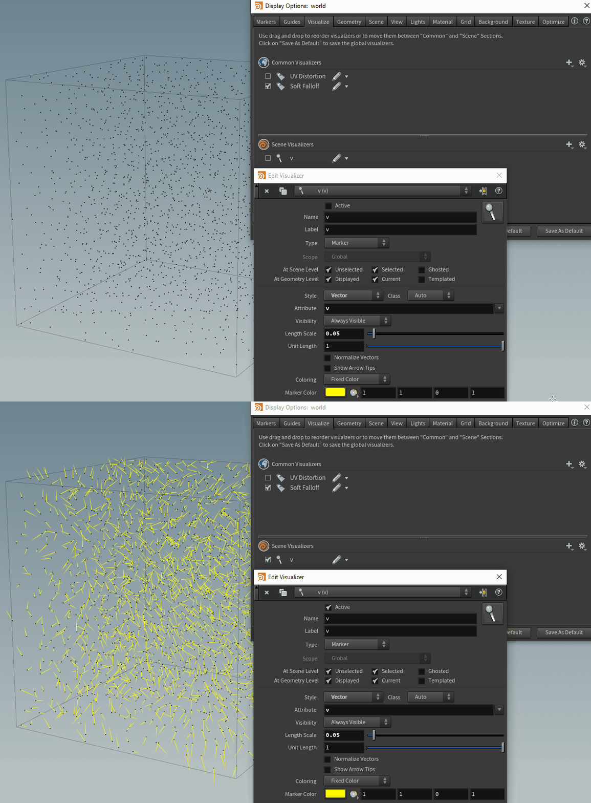
You can visualize an attribute if you add it to the Scene Visualizer, in the Display Options' Visualize tab.
You can open the Display Options just pressing the "d" key while your mouse is hovering the scene view; color, size and style can be adjusted.


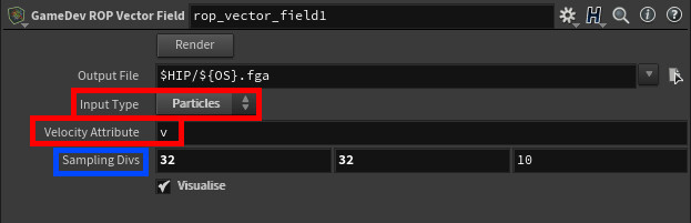
Now the only thing left is to generate the vector field using the GameDev node, change the input type to "Particles" and insert the attribute name you are using on the points for the "Velocity Attribute".

You can also change the resolution of the generated vector field with the "Sampling Divs" parameter. However, remember that if you increase it you might have to also increase the number of points initially scattered. it's probably not essential since we're just dealing with some simple noise here, but if you are generating more advanced vector fields you'll need more points to achieve a more accurate result.

As mentioned before, you can play around with the size and type of noise to achieve different effects. Once you're happy with it you just need to hit the Render button to export the fga file.


Vector Field from a Volume

To generate a Vector Field using a volume you first need to make a volume (what a surprise).
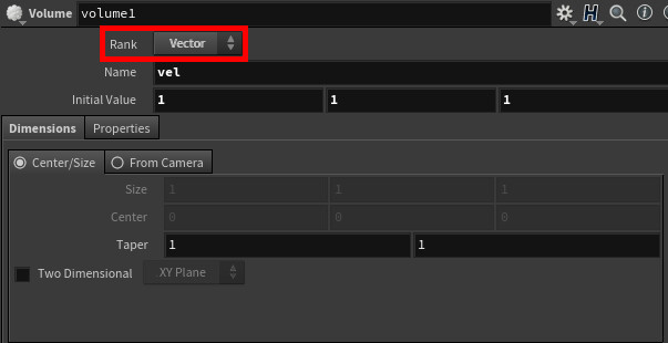
Make sure you change the "Rank" parameter from "Scalar" to "Vector", I'm also changing the initial values to 1 so that I can visualize the volume in the Scene View, but that's not essential.


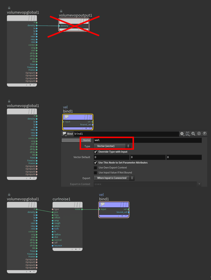
To add noise we can use a Volume VOP. Open it and replace the output node with a Bind Export one, make sure you set the "Type" parameter to "Vector" and remember the name you are using, then you can connect the position to a curl noise node.


Now just add the Game Dev Vector Field node, insert the right name in the Velocity Volumes node and you are done.
Here you can also override the resolution of the field, however if you need to increase the resolution I would change the "Uniform Sampling Divs" parameter of the actual volume to get the best result.


Like before, feel free to play around with the noise type and frequency, when you are done just press the Render Button to export the fga file.
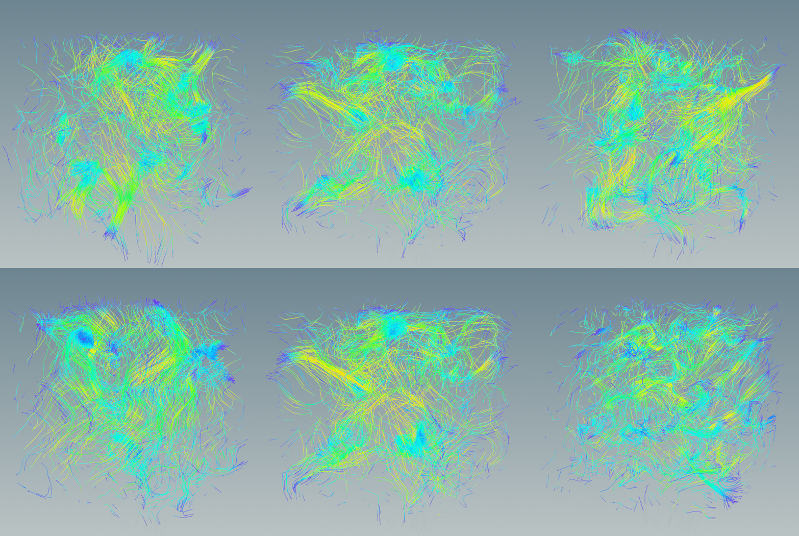
I did some tests and both ways for generating a vector field are valid, the results are similar so they are equally good, you can pick your favorite!


Bonus - Volume From Attribute

There is a 3rd way to simply generate a Vector Field, which kinda combines both the techniques described above. However, instead of using the Volume VOP you can use the Volume From Attribute node.
Here's the graph:


I hope this was somehow useful, feel free to share feedback and thoughts!

Report